CoreXY 3D Printer

A photorealistic rendering of a core-xy based 3D printer, designed in SOLIDWORKS.

The Engineering Process

Introduction

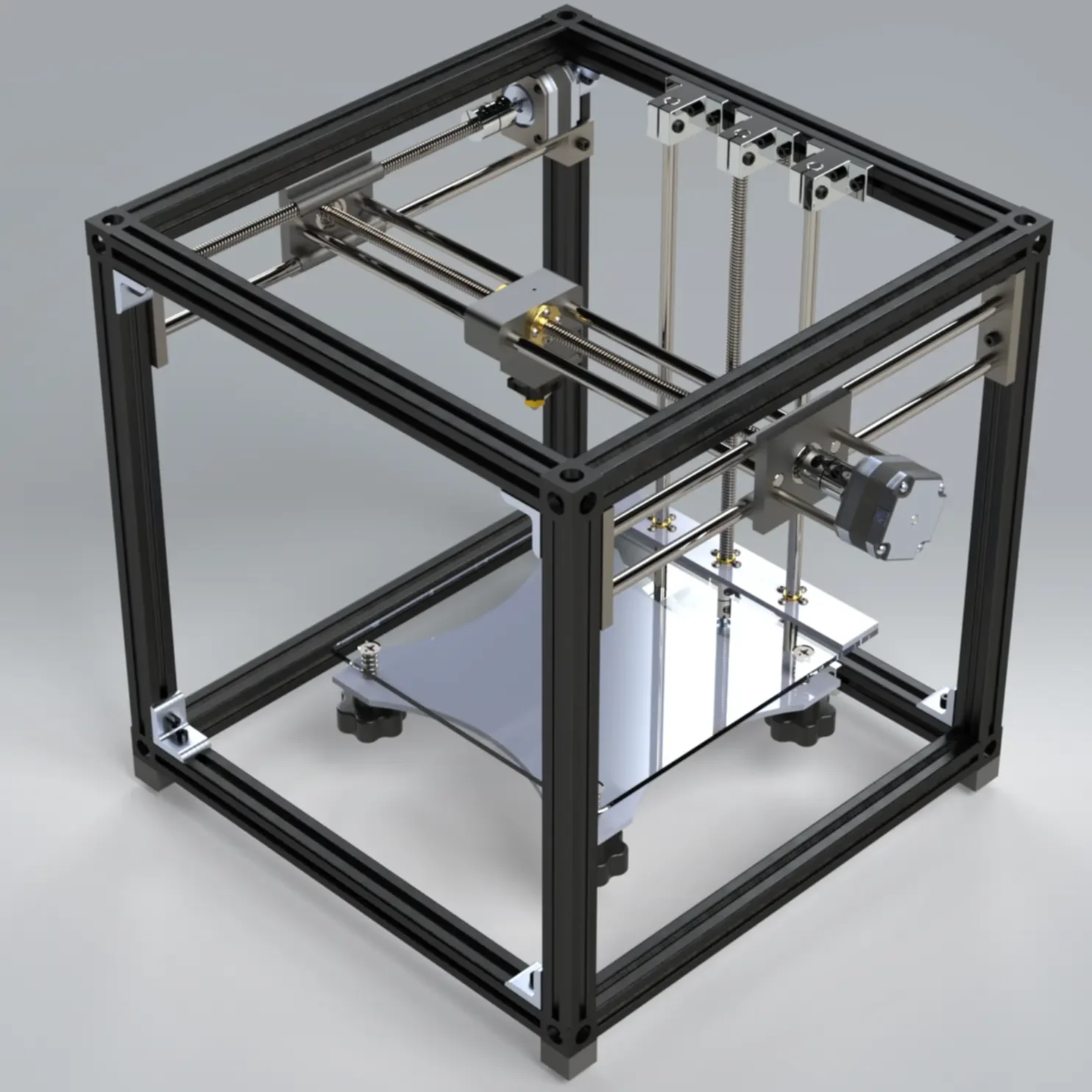
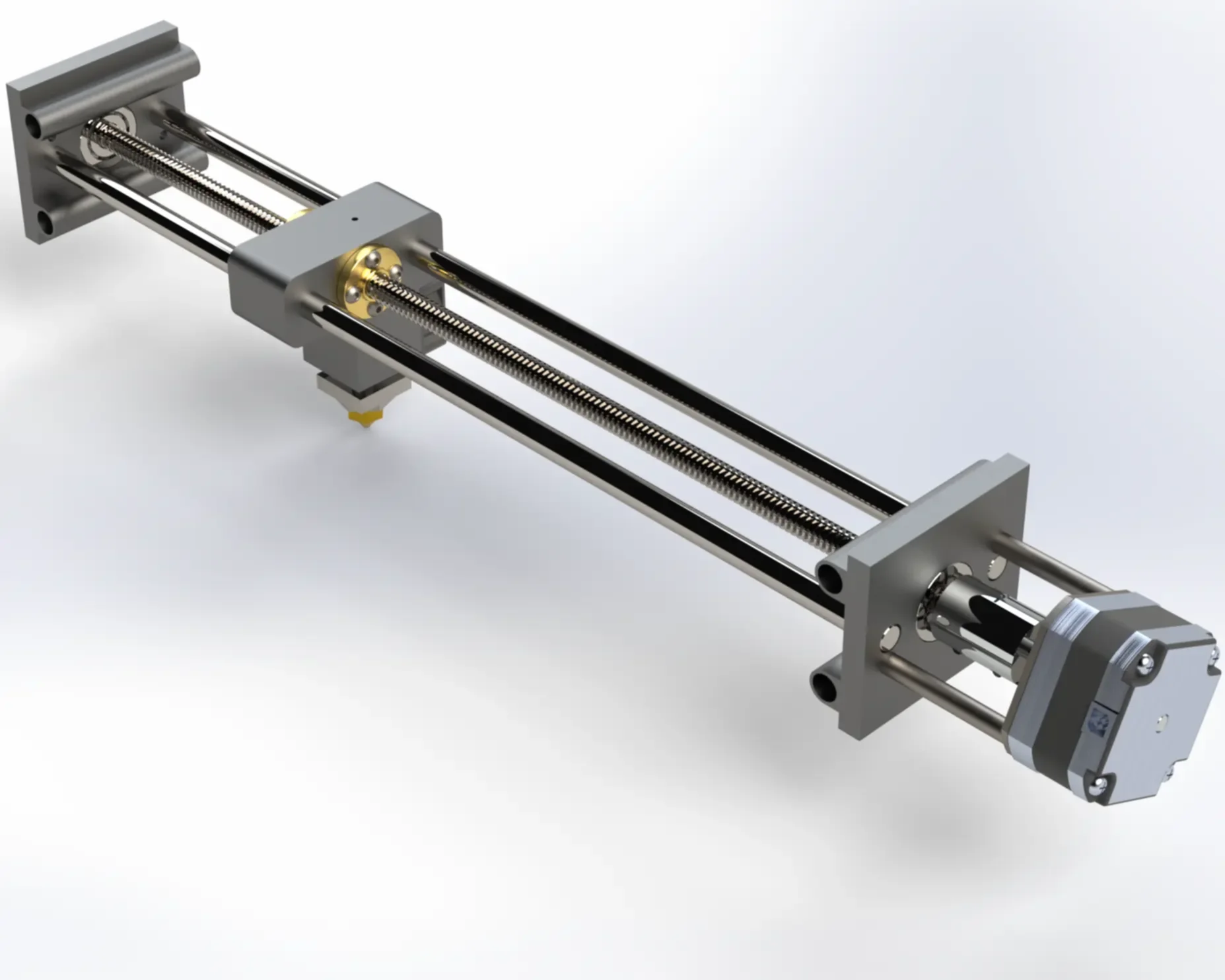
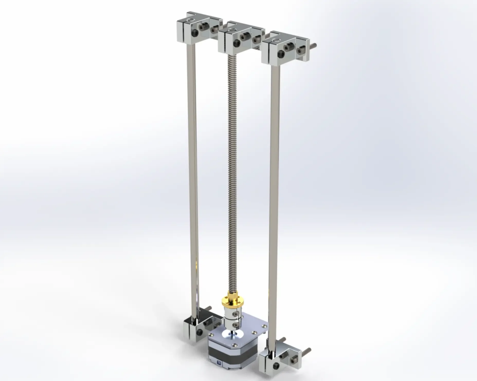
The goal of this project was to design a cost efficient entry level 3D printer with the target audience being an entry-level professional (engineer, designer, etc.) who needs rapid prototyping methods in their office. The instructions to the project can be found in the download link.

In addition to CAD models and technical drawings, we needed to create an engineering report outlining our design, and justifying our choices of parts, methods, etc.

This project had 6 members - Adli Hijab, Zein Barakat, Danny Jung, Fatima Hassan, Kisvah Kamal and myself. We split the tasks 
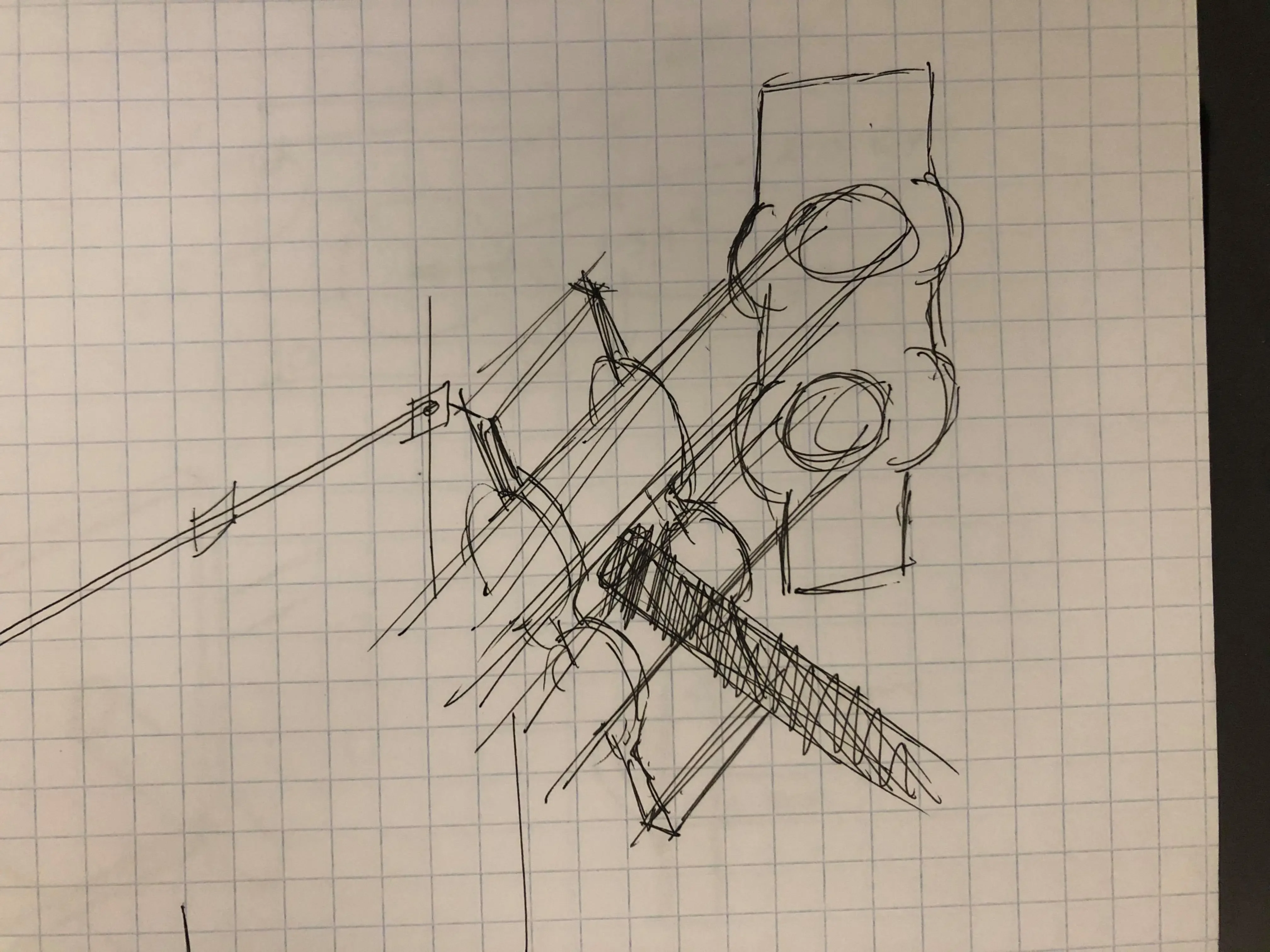
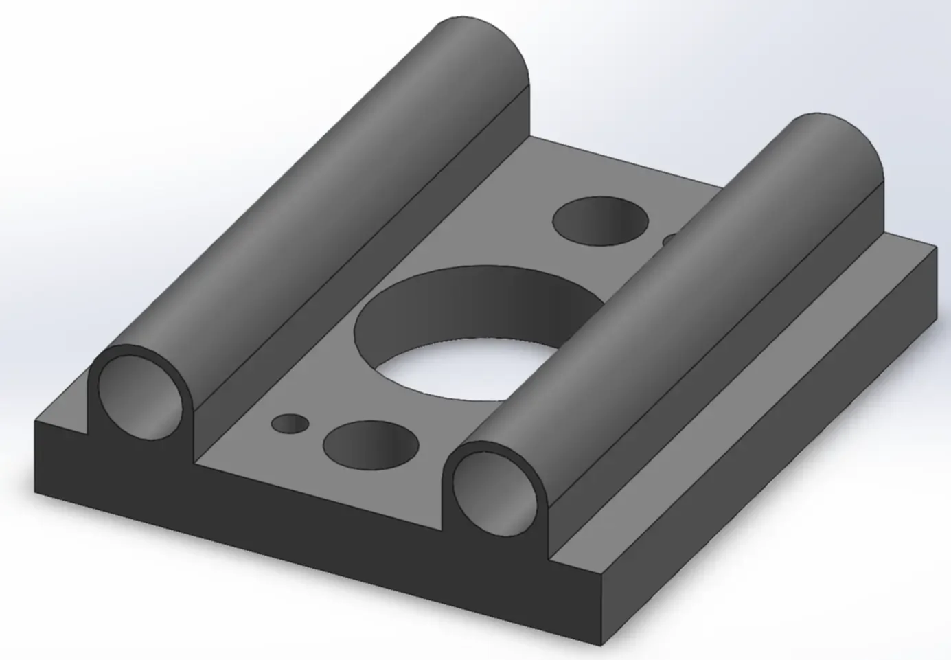
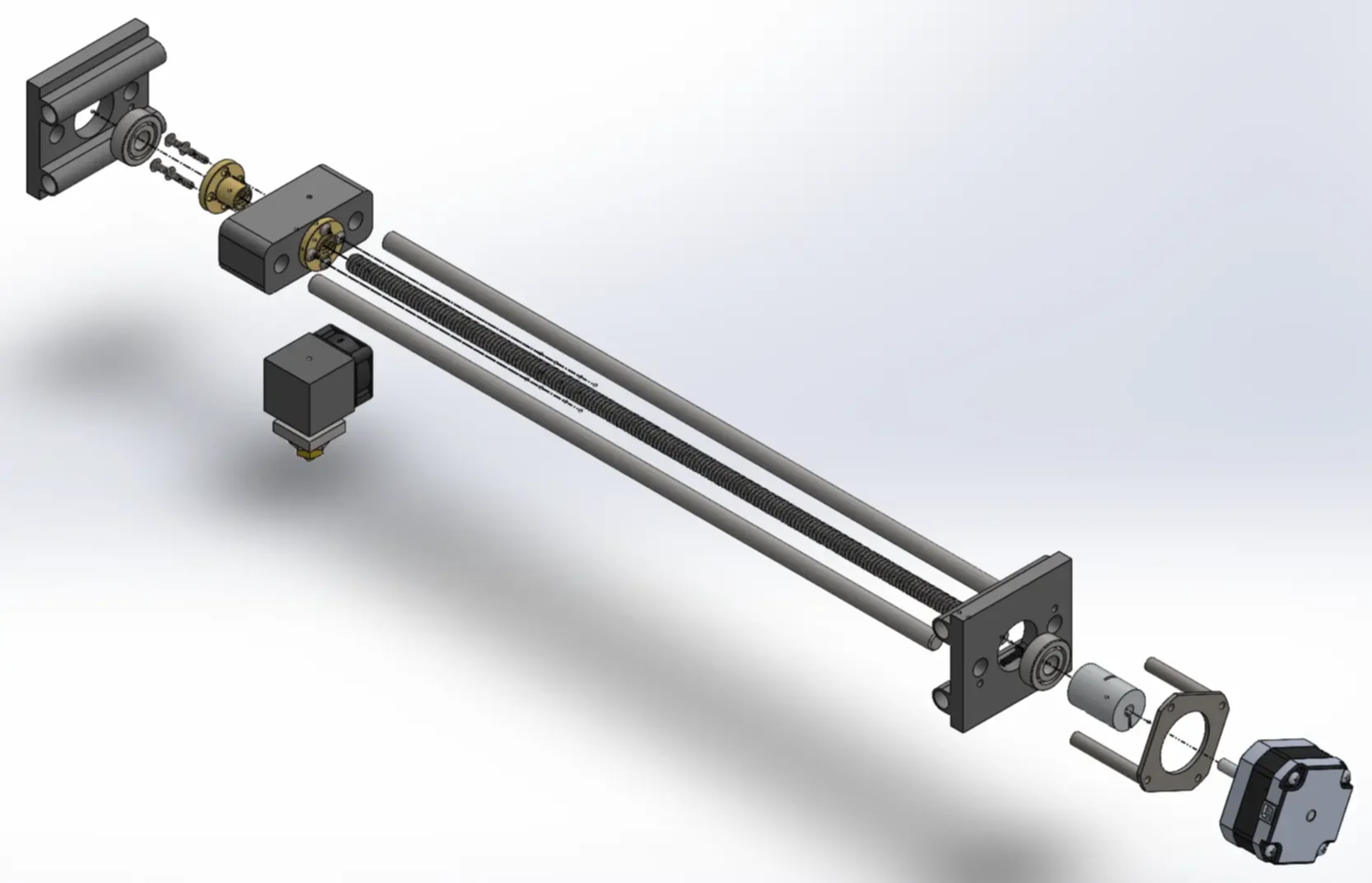
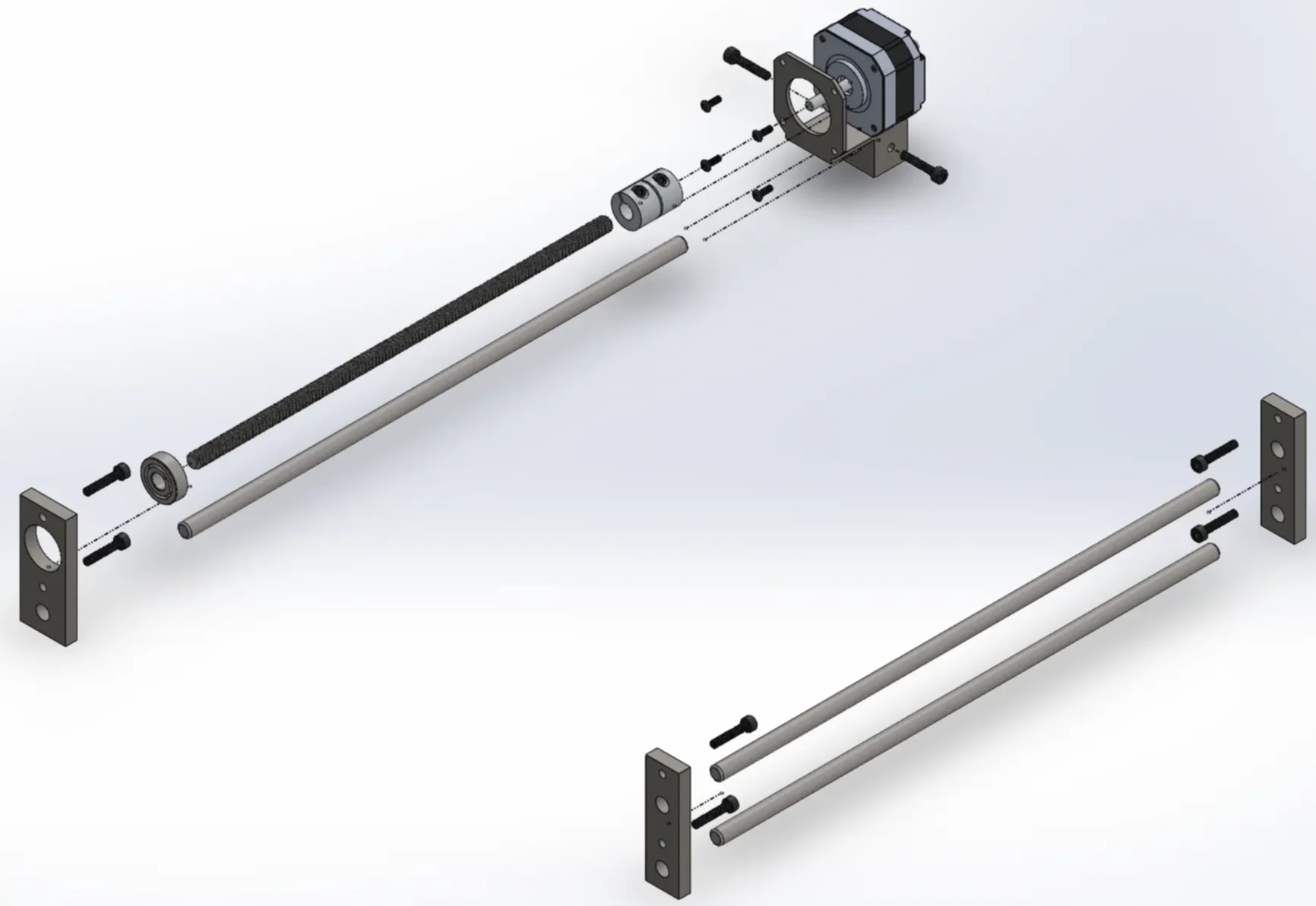
amongst ourselves - with me doing most of the CAD work and a few sections of the engineering report, and the rest of the group working on the engineering report. The tasks were delegated this way because I had extensive experience with 3D printers, and had access to my own Creality Ender 3 Pro 3D printer at home, which I could refer to for design inspiration and guidelines.

This page outlines my work in the project. It showcases the use of the iterative designing methods I learned in my 'MIE243 Mechanical Engineering Design' class to conceptualize and design parts.

Initial Candidate Designs

Step 1
My team and I began the process of creating multiple candidate (potential) designs and iterating on them. We realized there were many different types of 3D printers, so we took a few days to come up with individual designs. We would then go on to iterate on them, and eventually pick the candidate design we thought most suitable for our project requirements.

The following are images of my candidate design - which we decided to go with for the rest of the project. We decided to go with an FDM Core-XY based 3D printer. These drawings were created on my iPad.

Design Creation & Iterations

Step 2
Once we decided on which candidate design to move forward with, my teammate Danny Kung and I started working on the CAD model of the 3D printer. Using collaborative techniques, we iterated and went through multiple design phases - using methods taught in class, such as the black-box method.

To create the rough drawings of parts, we asked ourselves what functions the part would need to perform, what its input would be and what it would output. This thought process lead to many concepts, from which we chose the one we deemed most suitable, looking at it from a cost/weight/etc. perspective.

The following are some images of rough engineering drawings made while creating custom parts for the 3D printer:

CAD Models Creation & Iteration

Step 3
Steps 2 and 3 were interlinked processes, but once my teammate and I could visualize a design of a custom part (through the rough technical drawings we made), I initialized the CAD creation process.

Our project utilized SOLIDWORKS for CAD modelling, technical drawings, and some cost estimations.

The following are some of the custom parts we created using SOLIDWORKS, as well as some technical drawings. All the files can be downloaded from the link at the top of the page.

Final CAD Design & Engineering Report

Step 4
After countless hours of design and iteration, my teammate and I finished the working CAD model of the 3D printer - with appropriate SOLIDWORKS mates allowing for realistic movement of all the mechanisms.

Upon completion of the CAD model, we created all the technical drawings - all of which can be found in the downloadable folder.

The following are some of the final renders of the 3D printers, created using SOLIDWORKS Visualize: